Configuration options associated with this functionality: Use this module to perform the following operations:
Creo Show Sketch In Drawing, Right now they are just empty circles that i have changed the line color to black. Hide objects in a viewport�s drawing list. On the sketch tab, click line.

Creo parametricoffers functionality to work with engineering drawings in drawing mode with the detail module. Isometric scale does not matter as long as it does not interfere with the front, top and right side views Put the sketch on a layer. Dimensions can be altered in the model and the change is reflected in the dimensions on the drawing, but it can also do this in reverse.
Solved Missing hidden lines in Creo 2.0 drawing PTC
Configuration options associated with this functionality: • export drawing files to other systems and import files into drawing mode. This is for creo 4.0. On the sketch tab, click circle. Dimensions can be altered in the model and the change is reflected in the dimensions on the drawing, but it can also do this in reverse. • dwg_sketch_diagonal_guideyes*/no — shows the diagonal guide when you sketch draft geometry in drawing mode.

Creating Dimensions and Centerline Tutorial 2 Creo YouTube, About the creo parametric drawing mode. A good draftsman will make its use to make a drawing neat and publish only necessary details. I feel like this should be a simple task, but i am stuck. Hide objects in a viewport�s drawing list. You do not know how?

How can you show a Cosmetic Thread in an assembly drawing, Check the direction of the arrow. Here is the video for you.feel free to contact me or leave a comment, or idea for another creo. I�ve made a sketch (model>datum>sketch) of a grid of circles on a flat plane. Creo parametricoffers functionality to work with engineering drawings in drawing mode with the detail module. • dwg_sketch_diagonal_guideyes*/no — shows the diagonal.

How Can Creo 4.0 Improve Your 2D Drawing Annotations?, Creo drawing a centerline creo sometimes will not provide a centerline for your orthographic layout because it does not see it as a full 360 degree arc. About the creo parametric drawing mode. Put the sketch on a layer. Use this module to perform the following operations: How to create hatching for 2d sketch and some other nice creo tips#creo.

Solved Missing hidden lines in Creo 2.0 drawing PTC, About press copyright contact us creators advertise developers terms privacy policy & safety how youtube works test new features press copyright contact us creators. You do not know how? Which is used to include the 3d section view in the drawing. I�ve made a sketch (model>datum>sketch) of a grid of circles on a flat plane. The letter combinations define the.

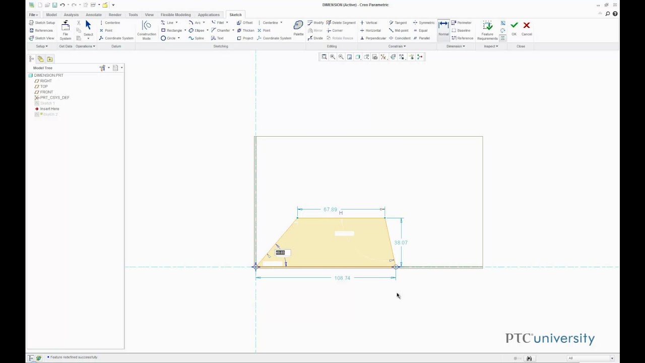
Adding Dimensions to a Sketch in Creo Parametric 2.0 YouTube, Then, click and drag your mouse on the datum plane to create lines. Isometric scale does not matter as long as it does not interfere with the front, top and right side views Unfortunately the sketches don�t show up on any layer (which is a bit confusing). To learn more, click here. Also within creo and solidworks the dimensions are.

Parts not showing up on drawing. PTC Community, Sketching the circle and cutout. Configuration options associated with this functionality: I feel like this should be a simple task, but i am stuck. Show single objects in a viewport�s drawing list. If the view isn�t shaded, the decal won�t display.

Starting a Drawing with Creo Parametric YouTube, In the drawing, blank the layer for the drawing, but select the view and show the layer in that view. Then in one drawing blank that layer, and in the other unblank it. Put the sketch on a layer. In creo and solidworks you can show dimensions from the any element of the model tree, making drawings very easy to.

How to draw PCD in Creo Drawing/ Drafting YouTube, The letter combinations define the symbol type, and the number is a unique identifier for the dimension. • dwg_sketch_diagonal_guideyes*/no — shows the diagonal guide when you sketch draft geometry in drawing mode. Display a viewport�s drawing list. Clear a viewport�s drawing list. How to create hatching for 2d sketch and some other nice creo tips#creo #creoparametric #creotutorial #tutorial #4kside #vpalffy.

CREO 2 Tutorial Creating Technical Orthographic Drawing, Do you need to create creo drawings view? On the sketch tab, click line. • export drawing files to other systems and import files into drawing mode. Creo parametric displays all items on model layers in the drawing, and you can manipulate the items separately at the drawing level. Right now they are just empty circles that i have changed.

Creo 4.0 2D 3D Detailing Improved Dimension Text in, Creo parametricoffers functionality to work with engineering drawings in drawing mode with the detail module. Creo parametric displays all items on model layers in the drawing, and you can manipulate the items separately at the drawing level. Then in one drawing blank that layer, and in the other unblank it. Check the direction of the arrow. Display objects with shadows.

Creo How to set Number of Decimal for Dimension in, Creo parametricoffers functionality to work with engineering drawings in drawing mode with the detail module. Configuration options associated with this functionality: It has to be the decal feature, on a shaded view. How to create hatching for 2d sketch and some other nice creo tips#creo #creoparametric #creotutorial #tutorial #4kside #vpalffy #vladi. Once the views are in their final place then.

Solved Change dimension preferences PTC Community, In creo and solidworks you can show dimensions from the any element of the model tree, making drawings very easy to generate. Then, click and drag your mouse on the datum plane to create lines. How to show model dimensions in the drawing. Show objects in a viewport�s drawing list. To learn more, click here.

How to create part drawing in creo YouTube, If it�s just an image in a sketch and the decal feature hasn�t been used on it, then it�s not a decal at all as far as inventor is concerned, so it won�t show either. Also within creo and solidworks the dimensions are two way parametric. Use this module to perform the following operations: • export drawing files to other.

New to Creo 4.0 Creating & Editing Geometric Tolerances, About the creo parametric drawing mode. Which is used to include the 3d section view in the drawing. On the annotate tab, in the parameters group, click switch symbols to show the dimension symbol, and identify the symbol type. Display a viewport�s drawing list. A good draftsman will make its use to make a drawing neat and publish only necessary.

Creo Part Drawing Dimensions FirstDemo YouTube, Dimensions can be altered in the model and the change is reflected in the dimensions on the drawing, but it can also do this in reverse. If your feature is less than 360 degrees then you will need to manually draw in a centerline. You can create a layer at the assembly or drawing level and add the sketch features.

How to create GD&T drawing in creo how to apply GD&T, Use this module to perform the following operations: Clear a viewport�s drawing list. Click sketch > snapping guides. • dwg_sketch_diagonal_guideyes*/no — shows the diagonal guide when you sketch draft geometry in drawing mode. • create drawings of all creo parametricmodels.

Lesson 10 pt1 Clamp Arm Drawing, Views, Dimensions PTC, Check the direction of the arrow. Matthew jourden brighton high school brighton, mi step 1: In your part create a layer called sketch and put the sketch in it. Then in one drawing blank that layer, and in the other unblank it. Creo parametricoffers functionality to work with engineering drawings in drawing mode with the detail module.

hidden lines in no hidden view PTC Community, Also within creo and solidworks the dimensions are two way parametric. Isometric scale does not matter as long as it does not interfere with the front, top and right side views It lets you add color and other visual enhancements to transform quick sketches into finished artwork. Creo sketch is a free 2d cad application that offers the easiest way.

Introduction to Drawings in Creo Parametric 2.0 YouTube, Clear a viewport�s drawing list. Creo drawing a centerline creo sometimes will not provide a centerline for your orthographic layout because it does not see it as a full 360 degree arc. I feel like this should be a simple task, but i am stuck. Click sketch > snapping guides. Hide objects in a viewport�s drawing list.

Syndeia for PTC Creo Intercax, You can create a layer at the assembly or drawing level and add the sketch features to that layer, then hide the layer. If your feature is less than 360 degrees then you will need to manually draw in a centerline. Configuration options associated with this functionality: • export drawing files to other systems and import files into drawing mode..
, Full")
Sections in CreoOffset, Zone Sections, Full(Unfold), Full, So that draw two straight lines passing through the keyway and fastener. Sketching the circle and cutout. I�ve made a sketch (model>datum>sketch) of a grid of circles on a flat plane. Deselect all of the data display filters options. Isometric scale does not matter as long as it does not interfere with the front, top and right side views

Quickly Replace the Model of a Drawing View YouTube, Display a viewport�s drawing list. Display objects with shadows and mirror. To learn more, click here. Check the direction of the arrow. Creo parametric displays all items on model layers in the drawing, and you can manipulate the items separately at the drawing level.

New to Creo 4.0 Add Images to Drawings YouTube, It has to be the decal feature, on a shaded view. Then in one drawing blank that layer, and in the other unblank it. About press copyright contact us creators advertise developers terms privacy policy & safety how youtube works test new features press copyright contact us creators. Configuration options associated with this functionality: If the view isn�t shaded, the.

Creo�s hidden lines YouTube, Creo drawing a centerline creo sometimes will not provide a centerline for your orthographic layout because it does not see it as a full 360 degree arc. In creo and solidworks you can show dimensions from the any element of the model tree, making drawings very easy to generate. Then right click all the new sketch entities and change linestyle.
, Full")
Sections in CreoOffset, Zone Sections, Full(Unfold), Full, Just turn the curves layer on, then use sketch > edge > use. Show objects in a viewport�s drawing list. Then, click on the datum plane and drag your mouse to create an oval. Creo drawing a centerline creo sometimes will not provide a centerline for your orthographic layout because it does not see it as a full 360 degree.