Lengt h of t ot al offset in direct ion of pipe run set: These small pipe pieces are termed piping spools.
Draw Rolling Offsets In Isometric Drawings By Sketching What, The technique is intended to combine the illusion of depth, as in a perspective rendering, with the undistorted presentation of the object’s principal. The complete piping system is separated into pieces that are transported to the site for erection. First, draw the main enclosing block, then draw the offset lines (ca and ba) full size in the isometric drawing to locate corner a of the small block or rectangular recess.
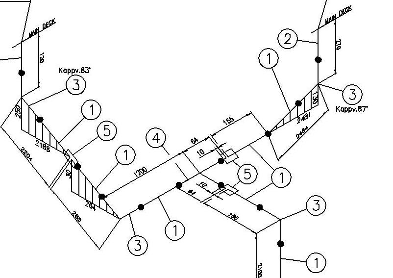
Locate main areas to be removed from the overall block. Use the method shown in figures 3.44a and b to locate points with respect to each other. To apply the settings to a previously generated isometric, the user will need to save the style configuration settings and regenerate the isometric(s). To indicate an offset, hatches on isometric drawings are applied, to indicate that a pipe runs at a certain angle and in which direction the pipe runs.
How to Get Angle Between ISO Axis and the Pipe for Rolling
Dept h of offset roll: All the best piping isometric drawing symbols pdf 40+ collected on this page. These measurements are called offset measurements. Offset is shown with a. Isometric drawings also inform which piping should be constructed at the fabrication shop and which should be assembled at the construction/platform field itself. These small pipe pieces are termed piping spools.

Pipe Rolling Offset Piping Analysis YouTube, Gear, chain & belt drives Piping fabrication work is based on isometric drawings. The technique is intended to combine the illusion of depth, as in a perspective rendering, with the undistorted presentation of the object’s principal. When an isometric is created offsets are depicted using hatched triangles/boxes such as the one shown below: When creating an isometric drawing in autocad.

How to Determined Vertical and Horizontal Shadow and with, Dept h of offset roll: Lightly sketch along isometric axes to define portion to be removed. A line created from one point 3 inches at 180 degrees would be a ________ line. To apply the settings to a previously generated isometric, the user will need to save the style configuration settings and regenerate the isometric(s). Rolling of in isometric drawing.

UseOffsetLineInsulation สอน AutoCAD Plant 3D โดย อ.เชษฐ์, 50+ isometric drawing exercises page 21/39. Piping isometric drawing consists of three sections. All the best piping isometric drawing symbols pdf 40+ collected on this page. Main graphic section consist of isometric representation of a pipe line route in 3d space, which […] When angle b is used, a is the side adjacent (sa) and b is the

sloping pipe in revit/Offset in isometric drawing/pipin, Lightly sketch along isometric axes to define portion to be removed. The complete piping system is separated into pieces that are transported to the site for erection. Please see the video to see the app in action. Use the method shown in figures 3.44a and b to locate points with respect to each other. When angle b is used, a.

Piping Isometric Drawing Offset and Rolling Offset Reading, Isometric drawings also inform which piping should be constructed at the fabrication shop and which should be assembled at the construction/platform field itself. The complete piping system is separated into pieces that are transported to the site for erection. Here’s how to use spoolfab to draw the offsetbox shown in the sketch below. Use the method shown in figures 3.44a.

How to drawing Isometric Rolling, Horizontal and, An isometric drawing allows the designer to draw an object in three dimensions. Isometric drawing rolling template.how to read isometric rolling offset.in हिन्दीhello friends आज की हमारी इस विडियो में बताया. Lightly sketch along isometric axes to define portion to be removed. It is the most important deliverable of piping engineering department. In this drawing, the rolling symbol is given,.

Piping drawing and symbols, Draw a piece of 10 inch pipe pointing straight. Piping fabrication work is based on isometric drawings. Rather than a horizontal or vertical triangle, the rolling offset requires an isometric box for proper dimensioning. I need to draw a rolling offset of a piece of 30 round duct. Breadt h of offset travel:
IPD and Revit Part VI Fabrication Drawings — Brett Showers, As a result, existing autocad commands such as line and copy are used for producing isometric drawings. A line created from one point 3 inches at 180 degrees would be a ________ line. Lightly sketch along isometric axes to define portion to be removed. These small pipe pieces are termed piping spools. Dept h of offset roll:

double rolling in piping isometric/wire bending isometric, An isometric drawing allows the designer to draw an object in three dimensions. What it needs to do is connect 2 pieces of straight that are offset to the side and at different elevations. 50+ isometric drawing exercises page 21/39. Rolling of in isometric drawing. Select axes along which to block in height, width, and depth dimentions.

gym equipment Multiview and Isometric Drawings by Tony, Trouble is, i am using a 3rd party software that is autocad based and i cannot figure out how to come up with angles to get the connection to work. These small pipe pieces are termed piping spools. Rather than a horizontal or vertical triangle, the rolling offset requires an isometric box for proper dimensioning. Main graphic section consist of.

PipingHow to Read Pipe Rolling/Offset in Isometric, Use the method shown in figures 3.44a and b to locate points with respect to each other. Sin = so/hyp “trig” function formulas: Locate main areas to be removed from the overall block. The settings below define how the rolling offsets are represented in the isometric. Lengt h of t ot al offset in direct ion of pipe run set:

How to Get Angle Between ISO Axis and the Pipe for Rolling, Breadt h of offset travel: An isometric is the best place for representing and dimensioning the rolling offset. Gear, chain & belt drives The settings below define how the rolling offsets are represented in the isometric. These types of drawings resemble a picture of an object that is drawn in two dimensions.

Piping Isometric Drawing Pdf Download, It is the most important deliverable of piping engineering department. To apply the settings to a previously generated isometric, the user will need to save the style configuration settings and regenerate the isometric(s). Feel free to explore, study and enjoy paintings with paintingvalley.com Follow these steps to create an isometric drawing of the object shown below, which has normal surfaces.

Piping Isometric Drawing Exercises Pdf at GetDrawings, All the best piping isometric drawing symbols pdf 40+ collected on this page. Select axes along which to block in height, width, and depth dimentions. Lengt h of t ot al offset in direct ion of pipe run set: Locate main areas to be removed from the overall block. Trouble is, i am using a 3rd party software that is.

PipingHow to Read Pipe Rolling/Offset in Isometric, An isometric sketch is one of the types of axonometric drawings. Breadt h of offset travel: Isometric drawings are also called isometric projections. Calculating isometric offsets isometric drawing offsets there are three basic “trig” function formulas that are frequently used in piping: When creating an isometric drawing in autocad the drafter can utilize the dynamic input and polar coordinate system.

Isometric Drawing Rolling Position All Views Vedio YouTube, This kind of sketching is often used by illustrators, engineers that specialize in technical drawings. Dept h of offset roll: How to know the degree of rolling pipe in isometric pipe drawing. Isometric drawings are also called isometric projections. When creating an isometric drawing in autocad the drafter can utilize the dynamic input and polar coordinate system to place both.

How to Use Various Rolling Offset Options in OpenPlant, Dept h of offset roll: Please see the video to see the app in action. Rather than a horizontal or vertical triangle, the rolling offset requires an isometric box for proper dimensioning. Isometric drawings are also called isometric projections. Piping isometric drawing consists of three sections.

Pipes Drawing at GetDrawings Free download, An isometric is the best place for representing and dimensioning the rolling offset. Let’s assume that your north arrow points up and to the right. An isometric sketch is one of the types of axonometric drawings. What it needs to do is connect 2 pieces of straight that are offset to the side and at different elevations. A line created.

Sloping and rolling isometric pipe drawing direction, Main graphic section consist of isometric representation of a pipe line route in 3d space, which […] Follow these steps to create an isometric drawing of the object shown below, which has normal surfaces only. Rolling of in isometric drawing. This video explain how to understood piping rolling/offset in isometric drawings and pipe rolling north,east orientation An isometric is the.

How to Use Various Rolling Offset Options in OpenPlant, An isometric sketch is one of the types of axonometric drawings. Select axes along which to block in height, width, and depth dimentions. When an isometric is created offsets are depicted using hatched triangles/boxes such as the one shown below: Rolling of in isometric drawing. Cos = sa/hyp tan = so/sa when angle a is used, a is the side.

how to read Rolling/offset in isometric drawing Rolling, In this drawing, the rolling symbol is given, you can see a lot of lines, in which there is a whole lot drawn in it, it will be seen from where it is getting smaller and where it is growing, then the first direction is from the small side. An isometric is the best place for representing and dimensioning the.

Piping Isometric Drawing Exercises Pdf at GetDrawings, When creating an isometric drawing in autocad the drafter can utilize the dynamic input and polar coordinate system to place both vertical and horizontal lines. The other two types are dimetric and oblique sketches. Draw a piece of 10 inch pipe pointing straight. 50+ isometric drawing exercises page 21/39. When angle b is used, a is the side adjacent (sa).

Pipe Fitter Isometric Drawing tutorial/Offset/Rolling, Here’s how to use spoolfab to draw the offsetbox shown in the sketch below. Gear, chain & belt drives Isometric drawing rolling template.how to read isometric rolling offset.in हिन्दीhello friends आज की हमारी इस विडियो में बताया. When creating an isometric drawing in autocad the drafter can utilize the dynamic input and polar coordinate system to place both vertical and.

Double rolling in piping isometric/isometric drawing, The complete piping system is separated into pieces that are transported to the site for erection. To indicate an offset, hatches on isometric drawings are applied, to indicate that a pipe runs at a certain angle and in which direction the pipe runs. Trouble is, i am using a 3rd party software that is autocad based and i cannot figure.

Are You Experience Piping Interview? YouTube, Trouble is, i am using a 3rd party software that is autocad based and i cannot figure out how to come up with angles to get the connection to work. The complete piping system is separated into pieces that are transported to the site for erection. Piping isometric drawing consists of three sections. In this drawing, the rolling symbol is.


