This command adds material in the third direction, a direction other than the sketch. We encourage you to visit, invite you to participate and look forward to your input and opinions.
How To Draw 3D Sketch In Catia, Green and yellow means fully constrained.white is under constrained.red is over constrained. Here i chose a blank page. Start a new 3d sketch.

Editing and modifying sketches • catia v5 provides you with a number of tools that can be used to edit the sketched elements. Save as the drawing file to a.dxf file step 4: How to define a thin dashed line in vba code? Click on front view from the menu step 7:
Catia part tutorial with technical drawing in AutoCAD 3D
Acrobat 3d, autocad, catia, inventor, ironcad, creo, pro/engineer, solid edge, solidworks, and others. • these include trimming the sketches using the quick trim, breaking a sketched element, filleting the sketches, adding chamfer to the sketches, and so on. How to define a thin dashed line in vba code? That will show your sketch. Here i chose a blank page. To make a custom curve, go to the 3d model, make a new sketch on the outlet flange.

Practice 2 Draw of 3D figure using CATIA Tools. YouTube, A multiview drawing is one that shows two or more 2d views of a 3d object. Below is some code for linetype, but result is still filled line. That will show your sketch. You will get a view as shown. In catia v5, how to draft a 3d model into engineering drawing and give dimensions.

Catia part tutorial with technical drawing in AutoCAD 3D, But even more surprising is file size. Click on front view from the menu step 7: I�m trying to merge a drawing that has different line, curve and spline segments into a sole entity/figure, but i can�t find a tool that accomplishes this. Constraints, using the tools in the constraint toolbar, as shown in the figure. The simplest way to.

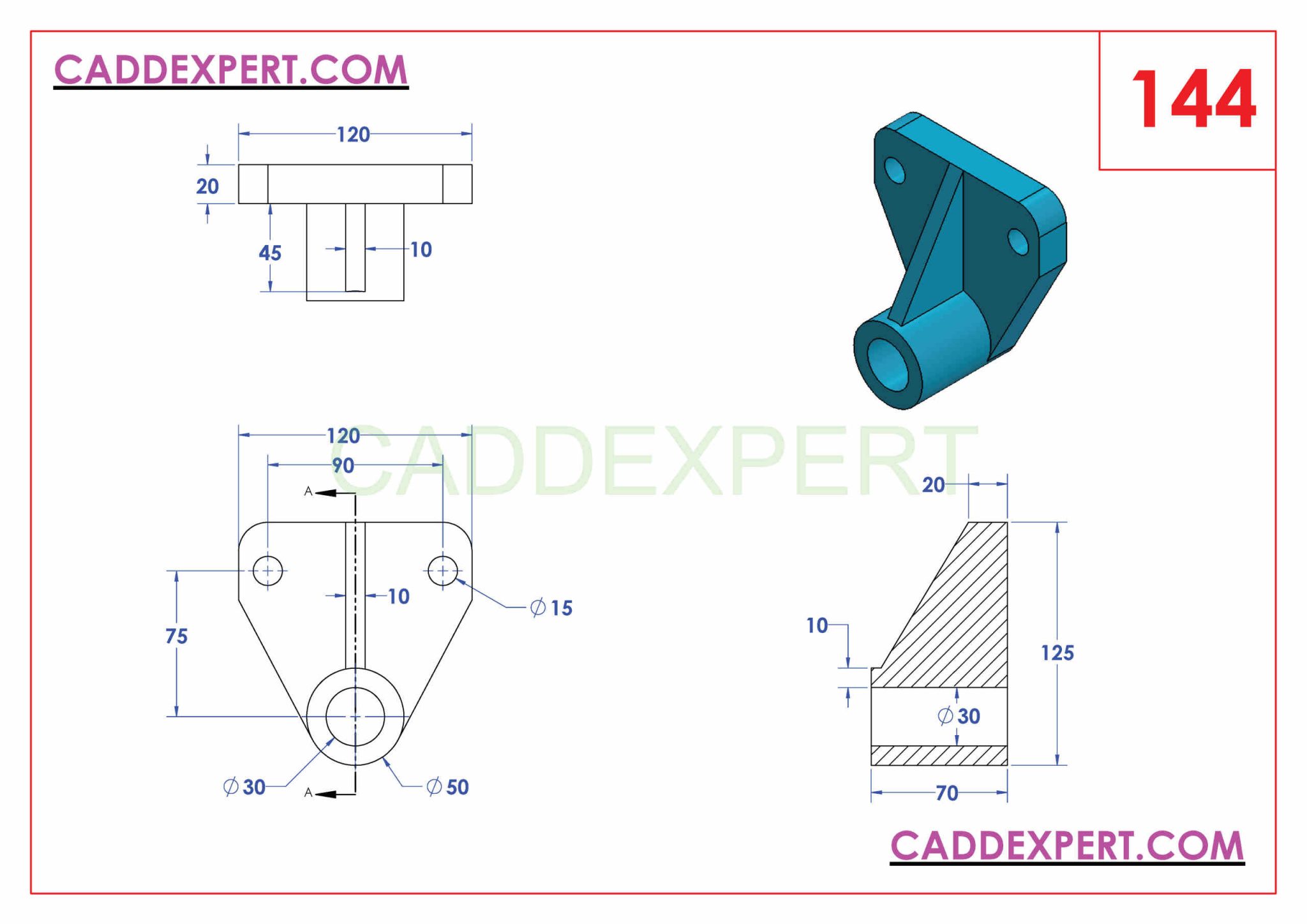
CATIA 3D DRAWING FOR PRACTICE Technical Design, November 7, 2011 in 1. How to define a thin dashed line in vba code? Trimming unwanted sketched elements • invoke the… We encourage you to visit, invite you to participate and look forward to your input and opinions. Learn about the grabcad platform get to know grabcad as an open software platform for additive manufacturing

CATIA V5 BLOG February 2014, How to define a thin dashed line in vba code? The user will first position and scale the image in 3d, then use shape design & styling. First define the points and. Click on the face as shown. Save as the drawing file to a.dxf file step 4:

Catia V5 TutorialHow to Read & Create 3d Models from 2d, A new drawing wizard opens up. Editing and modifying sketches • catia v5 provides you with a number of tools that can be used to edit the sketched elements. One of methods for text creation in catia v5 is to create text in catia drawing, save it as.dxf file, open.dxf file and copy text from drawing directly to catia sketch..

How to draw 3D modelsCATIA part Design PART 10 YouTube, This command adds material in the third direction, a direction other than the sketch. To make a custom curve, go to the 3d model, make a new sketch on the outlet flange. Open the saved dxf file and copy the text by selecting the whole text and clicking the copy icon as shown in the image step 5: You will.

CATIA 3D DRAWING FOR PRACTICE Technical Design, One of methods for text creation in catia v5 is to create text in catia drawing, save it as.dxf file, open.dxf file and copy text from drawing directly to catia sketch. We should be seeing this view in our drafting space after we click on the surface of the outer flange. Constraints, using the tools in the constraint toolbar, as.

sketcher catia CATIA V5 Sketch Workbench learn catia, Part design environment is used to create 3d models from the basic 2d sketches created in sketcher environment. How to define a thin dashed line in vba code? For 3d curve you have to use spline command in wireframe/gsd workbence. That will show your sketch. Some of the commands in workbench explained below.

CATIA 3D DRAWING FOR PRACTICE Page 2 of 2 Technical Design, You will get a view as shown. In the 3d sketch, click 3d sketch tab create panel intersection curve. Create a new drawing and create any text of any font and any text height step 3: Save as the drawing file to a.dxf file step 4: Join our cad community forums where over 25,000 users interact to solve day to.

CATIA V5 3D Practice Drawing No.7 Tamil YouTube, Set line11 = fact.createline (22.5, 9.25, 192.5, 9.25) line11.name = line11. We encourage you to visit, invite you to participate and look forward to your input and opinions. Learn about the grabcad platform get to know grabcad as an open software platform for additive manufacturing Place it on the blank page. What is the difference between split and trim in.

CATIA 3D Practice Simple 3D Drawing YouTube, In the 3d sketch, click 3d sketch tab create panel intersection curve. Click on the create an immersive sketch from paintings tool bar & select the image or the picture you want to trace and click on open. This product provides an intuitive toolbox for helping the user to convert 2d data into 3d data: Geometry copied into the part.

CATIA 3D DRAWING FOR PRACTICE Page 2 of 2 Technical Design, Green and yellow means fully constrained.white is under constrained.red is over constrained. Constraints, using the tools in the constraint toolbar, as shown in the figure. What is the difference between split and trim in catia? November 7, 2011 in 1. Learn about the grabcad platform get to know grabcad as an open software platform for additive manufacturing

Catia Drafting YouTube, Create a new drawing and create any text of any font and any text height step 3: Go to the part file , and open sketcher and paste the text. The simplest way to achieve this is to drag and drop the file directly into catia, which prompts the catdrawing window to load. Here i chose a blank page. Click.

12+ 3D Drawing Catia Drawings, 3d drawings, Learning, Trimming unwanted sketched elements • invoke the… Learn about the grabcad platform get to know grabcad as an open software platform for additive manufacturing In most cad software, the equivalent of this is called extrude, but in catia we call it pad. We encourage you to visit, invite you to participate and look forward to your input and opinions. By.

CATIA V5 3D Practice Drawing No.3 Tamil YouTube, Set line11 = fact.createline (22.5, 9.25, 192.5, 9.25) line11.name = line11. Place it on the blank page. This command adds material in the third direction, a direction other than the sketch. The simplest way to achieve this is to drag and drop the file directly into catia, which prompts the catdrawing window to load. Split in catia is used to.

CATIA V5/V6 Tutorial 3D Modeling from 2D sketch YouTube, November 7, 2011 in 1. We encourage you to visit, invite you to participate and look forward to your input and opinions. Trimming unwanted sketched elements • invoke the… First define the points and. That will show your sketch.

catia 3d drawing practice easy tips YouTube, Join our cad community forums where over 25,000 users interact to solve day to day problems and share ideas. First define the points and. Some of the commands in workbench explained below. Hello, i can not find how to adjust dashed line in drafting for catia. To make a custom curve, go to the 3d model, make a new sketch.

catia v5 2. drawing YouTube, For the view, properites viwe tab, turn on 3d wireframe. In most cad software, the equivalent of this is called extrude, but in catia we call it pad. But even more surprising is file size. Trimming unwanted sketched elements • invoke the… Make sure that the sketch is closed and not opened.

How to draw 3D models CATIA Exercisde Book Part 5 YouTube, Click on the create an immersive sketch from paintings tool bar & select the image or the picture you want to trace and click on open. Green and yellow means fully constrained.white is under constrained.red is over constrained. Generally, after drawing the sketch and applying the constraints, the sketch can exist in any one of the following. Hello, i can.

To MyCADnik CATIA V5 For Design / Inventor, Trimming unwanted sketched elements • invoke the… Hello, i can not find how to adjust dashed line in drafting for catia. Select the composite and the surface. Then go to our 3d model and choose the outlet flange surface as the “front view”. Save as the drawing file to a.dxf file step 4:

Tracing of SKETCH on a placed image in CATIA (3DSketch, Place it on the blank page. Green and yellow means fully constrained.white is under constrained.red is over constrained. Does catia v5 have an sketch tool equivalent to solidworks� fit spline? Here i chose a blank page. I�m trying to merge a drawing that has different line, curve and spline segments into a sole entity/figure, but i can�t find a tool.

Pin on 3d model, Constraints, using the tools in the constraint toolbar, as shown in the figure. Some of the commands in workbench explained below. Start a new 3d sketch. In catia v5, how to draft a 3d model into engineering drawing and give dimensions. Set line11 = fact.createline (22.5, 9.25, 192.5, 9.25) line11.name = line11.

CATIA 3D DRAWING FOR PRACTICE150 Technical Design in, For the view, properites viwe tab, turn on 3d wireframe. In most cad software, the equivalent of this is called extrude, but in catia we call it pad. Go to the part file , and open sketcher and paste the text. Use the sketch analysis tool to check if the profile(s) is closed, and if there are any extra geometry.


