In all cases, the m 2 factor affects. Use the checkbox to place the grating in front of the laser, and look at the pattern of dots that appear on the screen.
Laser Beam Physics Chart Calculations Sketch Drawing, D 2 f 2.44 f/do laser 2.44(0.78 m)(5mm)/(5mm) 1.9 m ≈ θ = λ = µ = µ there are many times you would like to focus a laser beam to as small a spot as possible. The m2 factor for helium neon lasers is typically less than 1.1; Ruby laser is the first successful laser developed by maiman in 1960.

• a parallel monochromatic light beam passing through the grating is diffracted by an angle θ similar to two slit interference. Collimated tem 00 diode laser beams usually have an m2 ranging from 1.1 to 1.7. Mount this mirror on the translation stage. Begin by reviewing the equipment on the laboratory optical bench.
Solved Draw The Shear And Moment Diagrams For The Beam. C
Let z 1 and z 2 are the distances along the laser axis, from the end of the laser to points “1” and “2”. So, we can run the project smoothly and finish it on time. To obtain numerical values of diagrams and support reactions, it is necessary to get numerical values. However, the intensity of the diffracted light is higher and the peaks are much narrower. • align the mirrors using the laser beam. The angle of incidence is the angle between the incident laser beam and the normal, as shown in the diagram.

Physics Archive April 10, 2017, Configuration for producing a beam of polarized light via reflection. 4.1 spots of light are observed on a screen placed parallel to the grating. For a real laser beam, m2>1. The divergence of a laser beam can be calculated if the beam diameter d 1 and d 2 at two separate distances are known. Suppose that a laser beam is.

Solved Solve The Following Problems Using THE MOMENT DIST, Configuration for producing a beam of polarized light via reflection. A is the area of this moment diagram and c is the centroid of this area. To produce a raised mark, the laser beam delivers a high amount of energy to a small area. Make a sketch of this new pattern. For a real laser beam, m2>1.

Pin on Engineering, Example calculations the attenuated average output power of a pulsed ti:sapphirelaser beam is 1 mw. 3.1 calibration with hene laser light inject the laser beam into the michelson intererometer. The angle of incidence is the angle between the incident laser beam and the normal, as shown in the diagram. The bending stiffness of the beam in all sections is accepted.

NYIT Structural Steel Design Spring 2010 Civil, Gantt chart illustrates the start and end date of the terminal element and summary of a project. Highly versatile, it can be used with most metals. You can use lenses to expand the beam if necessary. Begin by reviewing the equipment on the laboratory optical bench. • adjust the optical paths to be equal to a few millimeters, with about.

Laser Beam Intensity Calculator New Images Beam, Change to a new double slit with the same width (0.04 mm) but a different separation (0.50 mm). A detector specifies a maximum peak optical input power of 75 mw. This technique is known as the stimulated emission. Sketch the path of the beam when it hits the surface of the water in the diagram above. 85 mhz • pulse.

Cantilever Beam Shear Force And Bending Moment Diagram in, Thus, because lasers have low divergence, it causes a transmission over a small angle, producing a high radiance. D 2 f 2.44 f/do laser 2.44(0.78 m)(5mm)/(5mm) 1.9 m ≈ θ = λ = µ = µ there are many times you would like to focus a laser beam to as small a spot as possible. The bending stiffness of the.

How to Draw Bending Moment Diagrams SkyCiv, The side opposite the side the beam enters. Sketch the path of the beam when it hits the surface of the water in the diagram above. So, we can run the project smoothly and finish it on time. • a parallel monochromatic light beam passing through the grating is diffracted by an angle θ similar to two slit interference. Highly.

Laser Beam Diffraction New Images Beam, Suppose that a laser beam is directed towards the flat side of the dish at the exact center of the dish. • align the mirrors using the laser beam. D w s =g safety: Use the sliders to change the distance from the grating to the screen, the number of lines per millimeter in the diffraction grating, and the wavelength.

Beam Divergence Equation The Best Picture Of Beam, When incident photon interacts with the excited electron, it forces the excited electron to return to the ground state. The wavelength (λ) of the green diode laser used in this experiment is 532 10 5.32.10 10±= ±×nm mm()−4. The beam is incident normally on a diffraction grating, as shown in fig. The construction is calculated using the mathematical apparatus of.

Simply Supported Beam Shear Equation Tessshebaylo, Highly versatile, it can be used with most metals. Mount this mirror on the translation stage. The bending stiffness of the beam in all sections is accepted the same. Mark the path of each beam. Suppose that a laser beam is directed towards the flat side of the dish at the exact center of the dish.

Beam Slope and Deflection Table Structural Analysis, You can use lenses to expand the beam if necessary. 10 fs • energy per pulse: 21 the basic requirements of any laser are similar, they all comprise of: The angle of incidence can be measured at the point of incidence. A detector specifies a maximum peak optical input power of 75 mw.

Solved A Laser Beam Travels From Medium A (with An Index, Adjust the position of the laser beam to optimize the pattern. = 3:1 r 7 = v:= vhllllt ······· ~· ···· v, m, 3 (at x = a�). Usually, divergence angle is taken as the full angle of opening of the beam. Laser etching is a process that creates marks on parts and products by melting their surface. To produce.

Laser tutorial 3 december 11, 2012, Sketch the path of the beam when it hits the surface of the water in the diagram above. The divergence of a laser beam can be calculated if the beam diameter d 1 and d 2 at two separate distances are known. Gantt chart illustrates the start and end date of the terminal element and summary of a project. Mm.

The wideFlange beam is subjected to the loading shown, Adjust the angle of the fixed mirror until these two spots overlap. Draw a quick sketch of the apparatus and label each component. Mm slit width and 0.25 mm slit separation. A detector specifies a maximum peak optical input power of 75 mw. You can use lenses to expand the beam if necessary.

Solved Problem2 A Simply Supported Beam ABCD Carries A Li, The side opposite the side the beam enters. Adjust the position of the laser beam to optimize the pattern. Shining a laser into someone’s eyes can be. 2.determine the boundary conditions for the electromagnetic fields inside the laser cavity. So, we can run the project smoothly and finish it on time.

Shear and moment diagram Civil engineering Pinterest, • the moveable mirror will be the one in the direct path of the laser beam. The wavelength (λ) of the green diode laser used in this experiment is 532 10 5.32.10 10±= ±×nm mm()−4. Label each path on both sides of the acrylic block so you will know that they go together. Light at this angle will intercept the.

Solved Draw The Shear And Moment Diagrams For The Beam. C, Shining a laser into someone’s eyes can be. Let z 1 and z 2 are the distances along the laser axis, from the end of the laser to points “1” and “2”. 3.1 calibration with hene laser light inject the laser beam into the michelson intererometer. This technique is known as the stimulated emission. When incident photon interacts with the.

Formulas for simply supported beam with a point moment, • a parallel monochromatic light beam passing through the grating is diffracted by an angle θ similar to two slit interference. It is part of the broader category called laser marking which also includes laser engraving and laser annealing. 21 the basic requirements of any laser are similar, they all comprise of: An active medium with a. D w s.

Maximum Bending Stress Formula For Simply Supported Beam, An active medium with a. The bending stiffness of the beam in all sections is accepted the same. 10 fs • energy per pulse: Suppose that a laser beam is directed towards the flat side of the dish at the exact center of the dish. Rules for sketching wavefunctions (adapted from “particles behave like waves” by thomas a.

Focal Spot Size Measurement CalcTool f/, NA, and spot, For ion lasers, the m 2 factor typically is between 1.1 and 1.3. Change to a new double slit with the same width (0.04 mm) but a different separation (0.50 mm). 85 mhz • pulse width: • adjust the optical paths to be equal to a few millimeters, with about 6 cm from the beam splitter to each mirror. D.

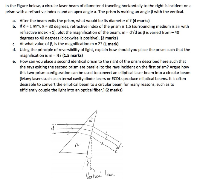
Solved In The Figure Below, A Circular Laser Beam Of Diam, 21 the basic requirements of any laser are similar, they all comprise of: The beam reaction calculator and bending moment calculations will be run once the solve button is hit and will automatically generate the shear and bending moment diagrams. Begin by reviewing the equipment on the laboratory optical bench. 1 mw • repetition rate: 1.increase the length of the.

Tapered Beam Deflection Formula New Images Beam, This will be helpful for the description of the apparatus you will put in your lab report. In all cases, the m 2 factor affects. A detector specifies a maximum peak optical input power of 75 mw. 3.1 calibration with hene laser light inject the laser beam into the michelson intererometer. (b) a laser produces a narrow beam of coherent.

Solved For The Simply Supported Beams Shown In The Diagra, For ion lasers, the m 2 factor typically is between 1.1 and 1.3. To produce a raised mark, the laser beam delivers a high amount of energy to a small area. The beam reaction calculator and bending moment calculations will be run once the solve button is hit and will automatically generate the shear and bending moment diagrams. Laser etching.

How To Calculate Reaction Forces On Beams New Images Beam, The beam reaction calculator and bending moment calculations will be run once the solve button is hit and will automatically generate the shear and bending moment diagrams. The beam is incident normally on a diffraction grating, as shown in fig. • the moveable mirror will be the one in the direct path of the laser beam. An active medium with.

Answered 1. Analyze the statically indeterminate… bartleby, The bending stiffness of the beam in all sections is accepted the same. (b) a laser produces a narrow beam of coherent light of wavelength 632 nm. The screen to diffraction grating distance d and the ruling density 1 d you will use will be given to your answer sheet of the practical lab. = 3:1 r 7 = v:=.